LiDAR overview
LiDAR stands for “Light Detection and Ranging” or “Laser Imaging Detection and Ranging” and is a distance measurement sensor that uses laser light. Originally called “laser scanners,” the term LiDAR came into widespread use after Velodyne launched “Velodyne LiDAR” for automated car driving systems in 2000. The basic principle of LiDAR and laser scanners is the same, but LiDAR is used for self-driving systems, while laser scanners are used for surveying systems and autonomous robots in factories and warehouses.
LiDAR is a TOF sensor that uses laser light with a wavelength close to that of visible light. For more information on the principle of TOF sensors, please refer to the Millimeter Wave Radar website (link).
The wavelengths used depend on the application. For example, 905nm and 1550nm are used for automated driving systems, 1064nm and 1550nm are used for topographical surveying on airplanes and drones, and 532nm and 640nm are sometimes used for architectural surveying in addition to the aforementioned wavelengths. In addition, 845nm is also used. Light is generated by using the quantum mechanical properties of matter. The wavelengths of light that can be handled depend on the properties of the materials, and cannot be freely determined by humans. The wavelength of the LiDAR product is selected based on the size and material of the object to be measured, the condition of the space (atmosphere) up to the object, the risk of human eyesight, the size and weight of the entire housing, and the balance with the cost structure of the final product.
Laser light is different from ordinary light in that it is a waveform of sine waves with aligned phases. The phase alignment is called the coherent state. Laser light is highly directional and can be pinpointed to a narrow area of an object. This helps to increase the spatial resolution of the ranging sensor. When generating light (electromagnetic waves) with wavelengths close to visible light, the generation process often depends on random physical phenomena, and the phases of the generated light are usually not aligned. In the case of laser light, the phase is aligned by using the mechanism of resonance reaction. In addition, the wavelength shift of the generated light becomes smaller due to the generation process. This characteristic increases the selectivity of the light emitted from the transmitter at the time of reception, and improves the sensitivity or signal-to-noise ratio (SN ratio).
Incidentally, when generating radio waves, an analog circuit is used to create a voltage waveform of a sine wave and transmit it directly to the antenna, so the phase of the sine wave is inevitably aligned. For example, the frequency of radio waves is in the order of 100GHz, which can be handled by analog circuits, but the frequency of visible light is in the order of 100THz, which is too fast to be handled. Therefore, light in the vicinity of visible light is generated by using physical phenomena.
Basic components of LiDAR
The basic components of LiDAR are a “laser” and an “optical sensor. As shown in the figure below, a laser beam is output from the laser, shines it on the object, and the reflected light is detected by the “optical sensor”. Although omitted in the figure, a lens is installed in front of the laser to increase the density of the laser light. Depending on the type of LiDAR, these lenses may be shared.
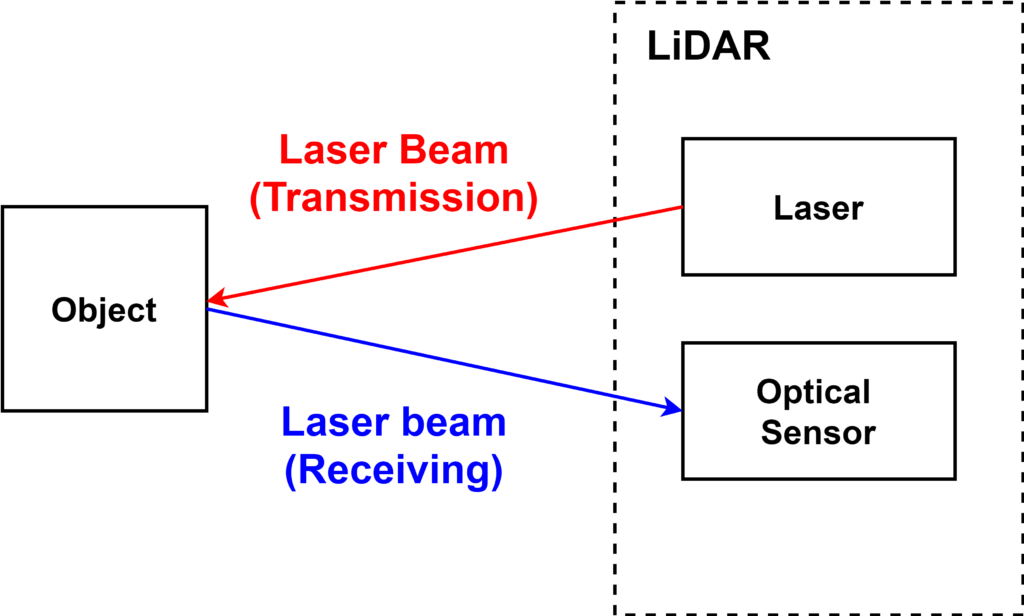
This is a TOF sensor that estimates the distance to an object by measuring the time between the output of a laser beam and its return. Assuming that the distance to the object is \(R\) (round trip distance is \(2R\)), time is \(\Delta T\), and the speed of light is \(c\), the following equation is established and the distance \(R\) is obtained.
$$~~2R = \Delta T \times c$$
$$~~R = \frac{\Delta T \times c}{2}$$
Semiconductor lasers are often used for LiDAR lasers for robots. Semiconductor lasers have the advantage of being smaller than other types of lasers. This is because they are strongly required to be small enough to be mounted on robots. The small size of the laser is also extremely important for LiDARs that use multiple lasers and LiDARs with a structure that rotates the laser itself, which will be introduced later.
Photodiodes are used in optical sensors. Photodiodes are semiconductor devices that convert light into electron and hole carriers (electric charges) through the photoelectric effect. CMOS image sensors, which are used as imaging devices in smartphones and digital cameras, are also included in the photodiode category. Image sensors are made up of multiple individual photodiodes arranged in a pixel pattern.
When a laser beam is irradiated, the light reflected back from the object is very faint and not easy to detect. If the intensity of the laser light can be increased, the intensity of the light to be detected can also be increased, but since too high an intensity of laser light is harmful to the human eye, the upper limit of the output intensity is set by law. However, if the intensity of the laser light is too high, it can be harmful to the human eye, so the upper limit of output intensity is set by law. For these reasons, focusing the light with a lens is not enough, and it is necessary to use an element with higher sensitivity than the photodiode used in cameras.
In addition, in general signal processing circuits, the signal from the sensor is amplified by an amplifier circuit so that it can withstand AD conversion, but in LiDAR, a higher SN ratio (signal-to-noise ratio) is often required. In such cases, a special semiconductor device called an APD (avalanche photodiode) is used as an optical sensor, which amplifies the amount of charge generated by the photoelectric effect in the photodiode. The APD is a device that combines a photodiode and an amplifier circuit. By integrating the photodiode and the amplification circuit, it is possible to suppress the effects of noise generated at the input of the amplification circuit, thereby improving the overall sensitivity of the optical sensor.
Output data of LiDAR
As mentioned in the previous section, the method of irradiating a laser beam and detecting the reflected light can only measure the distance in one direction. To be called LiDAR, the output data must be 2-D or 3-D. 2-D data is generally obtained by scanning in the “horizontal direction” and calculating the distance in each direction. A LiDAR that outputs 2D data is called a “2D LiDAR”. As an example, let’s consider a situation where a 2D LiDAR and an obstacle are in the following positional relationship.
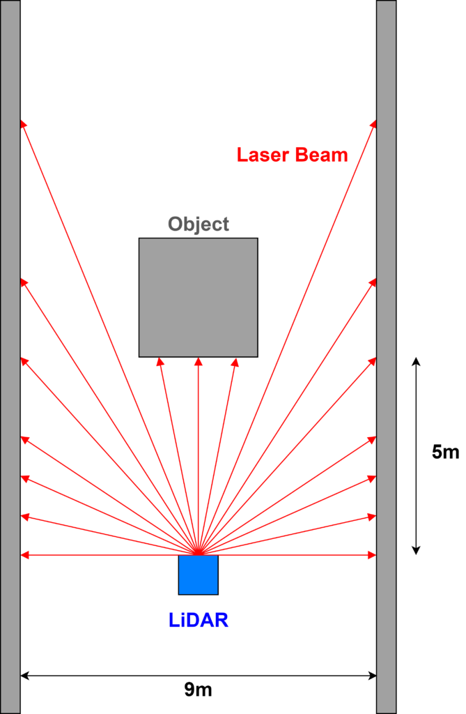
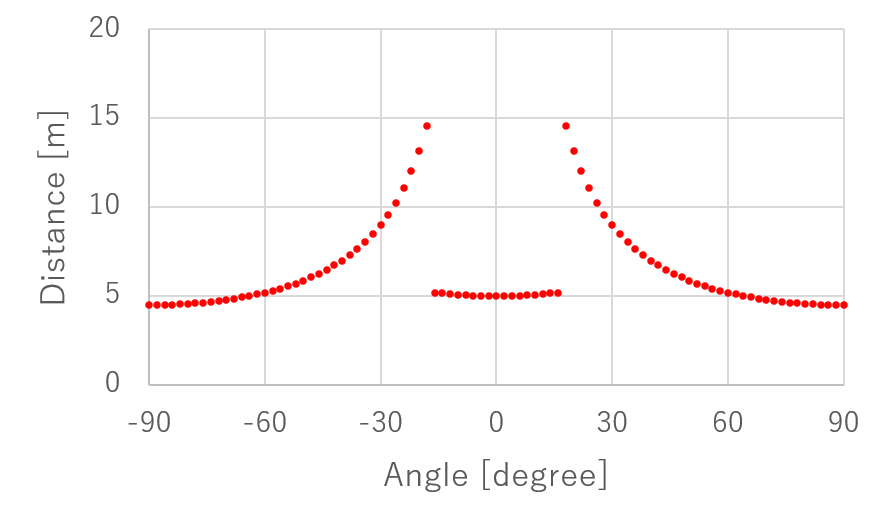
In this positional relationship, the distance is measured using 2D LiDAR and the resulting data is visualized in the graph below. When scanning the laser beam horizontally, some mechanism is used to rotate the laser and irradiate the laser beam intermittently in fixed angular steps. In this graph, it is assumed that the distance is measured by irradiating the laser beam in 1 degree increments. The front surface is set to 0 degrees, and the measurement range is ±90 degrees, for a total of 180 degrees. The measurement range depends on the LiDAR product and can be up to 360 degrees depending on the structure.
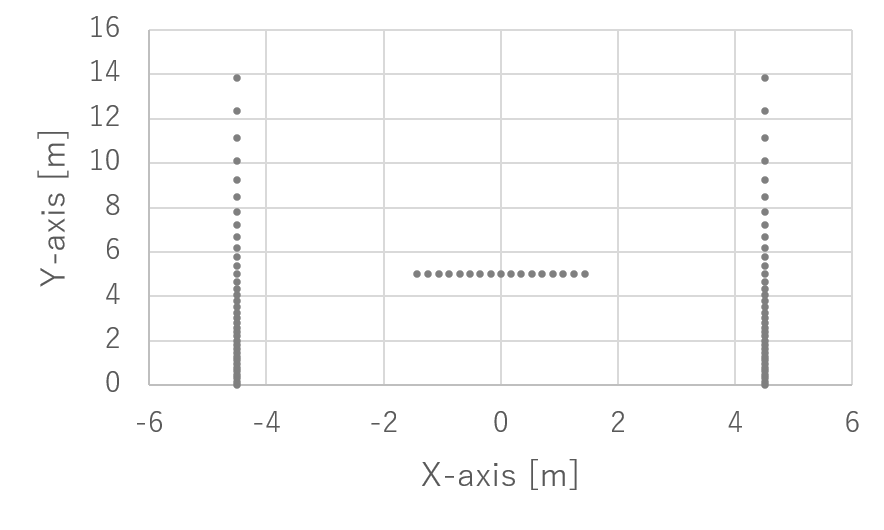
Using this data, let’s plot the location information of the obstacle on the two-dimensional planes of the X and Y axes. Assuming that the angle in the above figure is \(\theta\) and the distance is \(R\), the coordinates \((X, Y)\) are calculated as follows.
$$X = R~ sin(\theta)$$
$$Y = R~ cos(\theta)$$
Note that the general polar coordinates and the position (definition) of angle \ (\theta\) have been changed here, so the equation is slightly different. Using this formula, the above figure is transformed and drawn in the XY plane as shown below. Now we can get the positions of the obstacles that we originally assumed.
The next step is to visualize the 3D LiDAR data. For simplicity, let’s assume that there is only a frontal obstacle and the ground in the spatial positioning diagram described above. The height of the obstacle is 3m and the LiDAR is positioned at 1.5m above the ground. A plot of the data obtained under these conditions is shown in the figure below. The distance information is represented by colors. As shown in the color bar on the right, small (close) distances are shown in red, and large (far) distances are shown in blue. The distance in the direction where there is no obstacle is infinite, but for visualization purposes, we set the upper limit of the distance to 100m.

Let’s plot this data in 3-D space. Assuming that the horizontal angle is \(\theta\), the vertical angle is \(\phi\), and the distance is \(R\), the coordinates \((X, Y, Z)\) are calculated as follows.
$$X = R~ cos(\phi)~sin(\theta)$$
$$Y = R~ cos(\phi)~cos(\theta)$$
$$Z = R~ sin(\phi)$$
Using this equation, the above figure is transformed and drawn in the XYZ plane as shown below.

This figure was created by assigning points to the coordinates of where the laser beam hit the obstacle. This type of data is called a “point cloud”. 3D LiDAR generally handles the output data in point cloud. Each point is represented as an array (X, Y, Z, R) combining XYZ coordinates and distance R, and the data is composed by enumerating the number of points. The distance information is represented by color. To make it easier to see, the definition of the colors has been changed from the previous figure.
When 3D LiDAR is used in autonomous driving robots such as self-driving cars, it is processed to recognize a single obstacle by collecting points that are close in distance from the point cloud data to form a clump. This process can be a geometric calculation, a neural network calculation using deep learning, or a clustering process, one of the artificial intelligence technologies. The most common shape of an obstacle is a rectangle that fits the obstacle perfectly. If the obstacle is a car or a human, a rectangular shape is sufficient. On the other hand, if we want to have an autonomous vehicle with a robotic arm to grab objects in a factory or warehouse, we need to know the shape of the object in more detail. For this purpose, we can use 3D polygons, which have more vertices than rectangles, to recognize the shape of the obstacle.
Types of LiDAR structures
LiDAR is a sensor that obtains a map of distance information of an object by “scanning” the laser beam in horizontal or horizontal and vertical directions. As such, it requires the ability to irradiate the laser beam in multiple directions. In principle, it would be sufficient to have as many lasers as there are directions, but this is not a configuration that can be actively adopted because it would be too costly and the size of the LiDAR product would be too large. LiDARs are classified according to the way they irradiate the laser beam in multiple directions. I will now introduce them one by one. The names of the different types vary depending on the literature and websites, and there seems to be no standardization.
Flat mirror type
The “flat mirror type” LiDAR is a LiDAR that has a mechanism to irradiate the laser beam in multiple directions by shining the laser beam onto a single flat mirror and rotating the flat mirror. It is sometimes called a “tilt-mirror” type. The image is shown below.
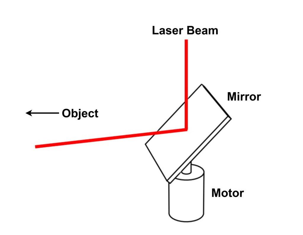
The mirror is fixed to the pillar at an angle to the horizontal direction, and the pillar is connected to the shaft of the motor. The mirror rotates as the motor rotates. The laser beam is irradiated from the top of the mirror, and the reflected light goes to the object. In the configuration shown in this figure, the vertical angle is fixed, and only the horizontal angle changes. The result is a distance information similar to the 2D LiDAR data described above. If the mirror is rotated 360°, the horizontal angle range is 0° to 360°. If the mirror is placed above the head of an autonomous robot, it will be able to detect obstacles in a 360° circumference.
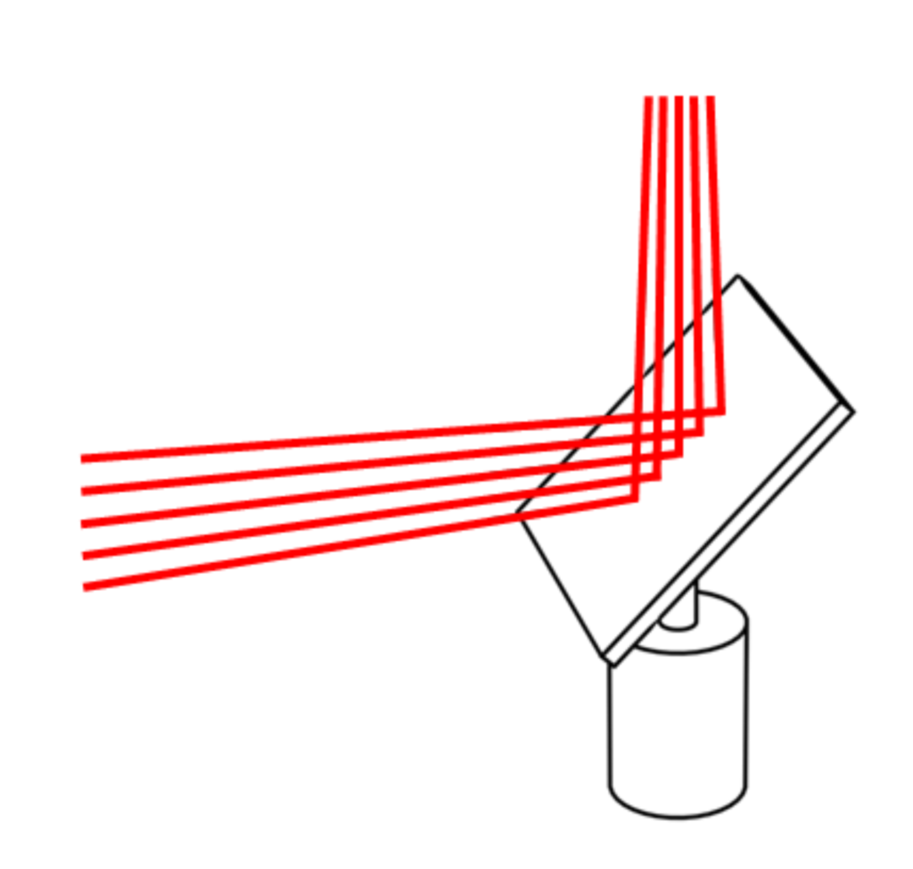
To make 3D LiDAR by also changing the vertical angle, increase the number of lasers by the number of angles you want. As shown in the figure below, irradiate the mirror with the laser beam at a slightly different angle in the vertical direction and reflect it. By rotating the motor in this state, distance information like the 3D LiDAR data described above can be obtained.
Polygon mirror type
The “polygonal mirror” LiDAR eliminates the disadvantage of needing to prepare multiple lasers of the planar mirror type. As the name suggests, a polygon-shaped mirror is prepared. An image of the structure is shown in the figure below.
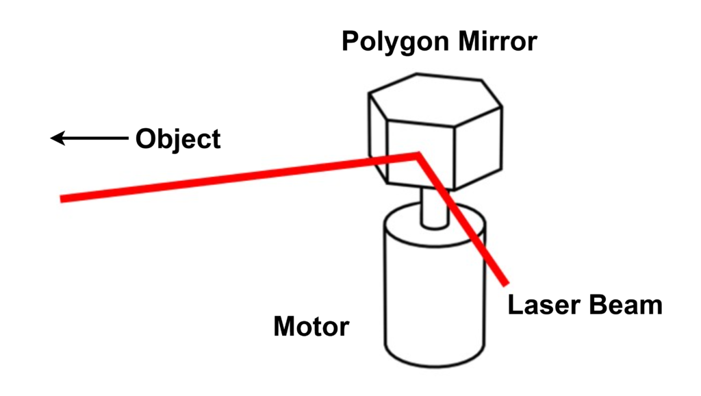
Prepare a structure consisting of six mirrors with slightly different vertical angles attached to their sides, and irradiate laser beams to the mirrors in the horizontal direction. By irradiating the laser beam from the horizontal direction to the mirrors with different vertical angles, the angle of reflection changes for each mirror and multiple vertical laser beams can be generated. Please refer to the figure below. This makes it possible to use only one laser, which was required for the number of vertical directions in the flat mirror type.
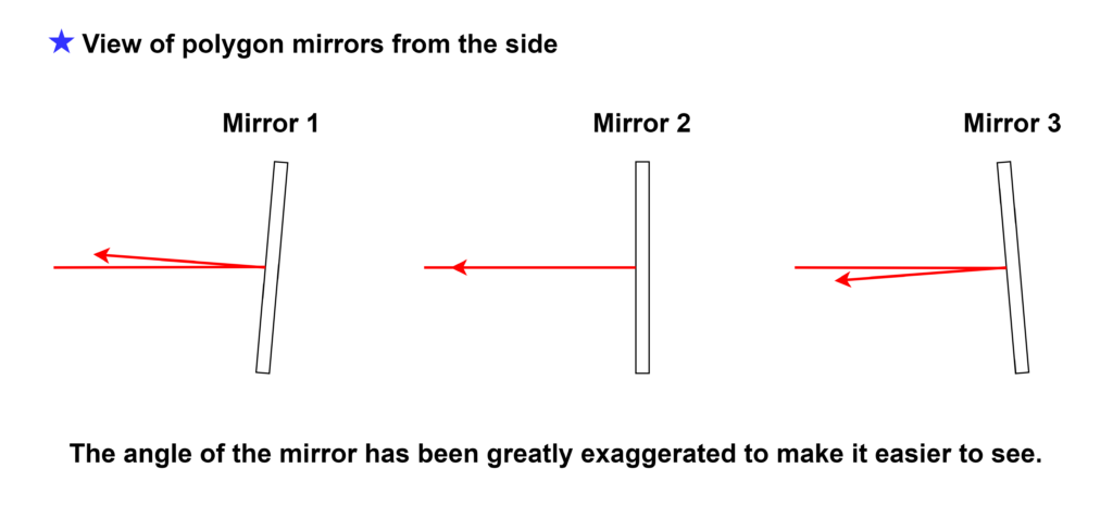
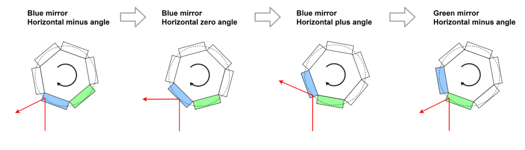
On the other hand, what is the horizontal angle? See the figure below. As with the flat mirror type, the horizontal angle can be changed by rotating the motor. However, unlike the flat mirror type, it is not possible to irradiate in a 360° direction. In the case of a hexagonal shape, the beam is irradiated in the direction of one-sixth (60°). The disadvantage of the polygon type is that the measurement range in the horizontal direction is limited as shown in the figure below.
Head rotation type
The head rotation type is a method in which multiple lasers are placed on a single pedestal and the whole thing is rotated by a motor to scan the laser beam horizontally. By slightly changing the vertical angle of each laser, it is possible to irradiate the laser beam in multiple vertical directions. This method does not use mirrors and irradiates the laser beam directly onto the object, which has the advantage of a simple structure and easy accuracy. On the other hand, since each of the multiple lasers is rotated by a motor, the weight of the rotating part is larger than in other methods, and a high-power (high torque) motor is required. The higher the power, the larger the size of the motor, and thus the larger the size of the LiDAR product as a whole. It also tends to be noisier and more expensive due to the use of multiple lasers.
The LiDAR made by Velodyne, a well-known company for automated driving, is a head-rotating type. It has a large share of the market for experimental vehicles, but due to the disadvantages mentioned above, it has not been adopted for use in regular automobiles.
Solid state type
Mechanisms that use motors to rotate mirrors and lasers tend to be large in size. Therefore, the development of “solid-state” LiDAR, which does not use a motor, is progressing. There are several types of solid-state LiDARs, but the representative one is the MEMS type, in which the mirror and the actuator that moves the mirror are manufactured using a semiconductor process, and the same functions as those of the flat mirror type are built microscopically into an LSI chip. This type of LiDAR can be made compact, but has the disadvantage that it is difficult to improve the positioning accuracy due to the microfabrication involved.
Another typical type of solid state type is the “flash type”. While the other types irradiate the laser beam locally, the flash type irradiates a wide area at once. In this way, the laser light reflected by the object comes back from multiple directions at once. In contrast, multiple optical sensors are arranged in a two-dimensional array (pixel-like) in the receiver to detect laser light from multiple directions simultaneously. This is the same mechanism used in ordinary cameras for visible light, where the flash is turned on to capture images. The difference is that in a normal camera, the amount of light received by each pixel is measured, while in a flash-type LiDAR, the timing (time) of light detection for each pixel is measured. multiple measurements based on the TOF principle are performed simultaneously.
The flush type has the great advantage that it does not use a mechanism that involves rotation and therefore does not deteriorate due to mechanical wear. This type is preferred in applications where service life is of particular concern, such as automobiles. On the other hand, there is a disadvantage in that the laser beam is irradiated in multiple directions at once, resulting in a higher output power per shot, which can be harmful to the human eye. (The intensity of the light output is regulated by law. (The intensity of the light output is regulated by law.) When the intensity of the light output is reduced, the amount of light reflected back becomes smaller, making detection more difficult and measurement accuracy worse. Research and development to overcome these disadvantages is being carried out by various companies and research institutes.
Circuit configuration of LiDAR
The main performance indicators of LiDAR are distance resolution, angular resolution, and measurable distance.
Distance resolution
The physical limit of the distance resolution of LiDAR is determined by the scale of the wavelength of the light to be irradiated and the measurement accuracy of the reception timing. 1000nm (1um) is the limit of the distance resolution for infrared light with a wavelength of about 1000nm, which is more than enough accuracy for the ranging function of a robot. The measurement accuracy of the reception timing refers to the time resolution of the TDC, which is basically a “counter. The basic structure of the TDC is a “counter”; for example, if the counter is operated by a clock with a period of 1ns (1GHz), the time resolution will be 1ns. This is the distance resolution.
$$R = \frac{\Delta T \times c}{2} = \frac{1[ns] \times 3 \cdot 10^{8} [m/s]}{2} = 0.15 [m] $$
Since digital circuits (CPUs, etc.) for computers, such as PCs, can usually achieve 3 GHz, assuming 3 GHz, the distance resolution is ⅓ of a cm. In LiDAR, the distance resolution is likely to be governed by the time resolution of TDC, not the wavelength length. However, if a digital circuit capable of operating at 3 GHz is fabricated in a semiconductor, a relatively fine process must be used, and the unit cost per semiconductor chip will be high. In order to avoid such a problem, TDCs are sometimes combined with analog circuits instead of consisting of pure counters to achieve high time resolution even at low clock frequencies. This type of TDC can achieve a time resolution of several tens of ps and a distance resolution of 1 cm or less.
In addition, if we use the “phase shift method” instead of the simple TOF method, which detects the phase difference of the light waveform, we can achieve a distance resolution of about 1mm.
Angular resolution
The angular resolution of LiDAR differs in the vertical and horizontal directions. The vertical angular resolution of the planar mirror type and head rotation type is determined by the pitch of the angle of the multiple lasers installed. If the vertical angle range is fixed, the angular resolution is the angle range divided by the number of lasers. In the case of polygon mirror type, the angular resolution is determined by the difference in the angle of each mirror.
The horizontal angular resolution is determined not by the structure but by the spread of the laser beam. If the laser beam can be directed to a narrow area with pinpoint accuracy, the angular resolution will be higher. However, the angular resolution is not determined only by the spread of the irradiated laser beam, since the surface material of the object reflects the light in various ways. In actual LiDAR products, the angular resolution can be as high as 0.1 degree.
Determination of the possible distance (maximum distance)
The measurable distance of LiDAR is determined by the competition between the amount of light received and the total noise level of the measurement environment and receiver circuit. This is because the farther away the object is, the smaller the amount of light that is reflected back. In principle, the higher the output power of the irradiated laser beam, the longer the measurable range will be, but since too much output power can be harmful to the human eye and skin, there are legal limits. However, if the output power is too high, it may be harmful to human eyes and skin. The actual LiDAR products seem to be around 300m.