Stereo Camera Overview
Stereo cameras are a type of distance measurement sensor. Since around 2000, they have been used to detect obstacles in order to realize safety driving support functions in automobiles and autonomous driving functions in robots. Subaru’s EyeSight is a famous example for automobiles.
Stereo cameras, as the word “stereo” implies, are made by combining two cameras. When two cameras are placed at a distance from each other, each camera will see the object differently, resulting in a slightly different image. This is called “parallax”. By measuring the amount of parallax, the distance to the object can be estimated (see below for details).
The calculation of the distance is done by inputting the images acquired by the two cameras into an image processing program (algorithm). This algorithm is called “stereo matching”. Stereo matching has been studied for decades, and around the year 2000, the processing performance of semiconductors that had been evolving up to that point reached the level required for stereo matching, and applications such as EyeSight became available in a form that was visible to the general public. Around the year 2000, the processing performance of the semiconductors that had been evolving until then reached the level required for stereo matching, and applications such as EyeSight began to be sold in a form that could be seen by the general public.
Basic structure of a stereo camera
The basic configuration of a stereo camera is shown in the figure below.
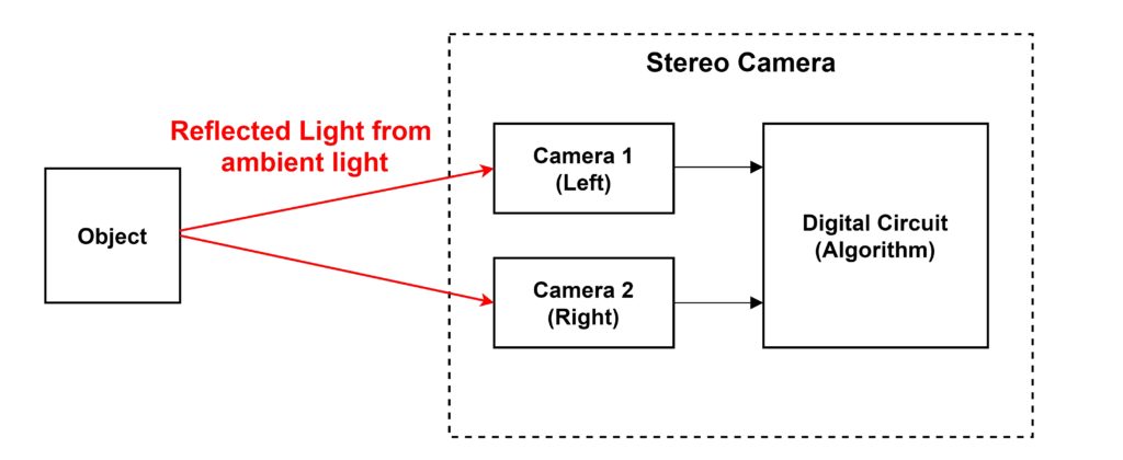
The image data captured by the two cameras at the same time is transmitted to some digital circuit, and the digital circuit executes the image processing algorithm for stereo matching. The digital circuit is equivalent to a microcontroller (CPU), FPGA, or ASIC (a dedicated LSI).
Unlike other ranging sensors such as millimeter wave radar and LiDAR, the sensor does not emit electromagnetic waves. It uses reflected light from sunlight or lighting on the object. Stereo cameras estimate distance based on the difference between the images of the two cameras, so they do not work at night or in dark rooms where there is nothing to see in the images. In such cases, the robot with the stereo camera can be illuminated with light. Since stereo matching has the feature of not being able to measure the distance of a plain object with no pattern, as described below, there are stereo cameras equipped with projectors that emit light to draw a pattern on the object. There are also stereo cameras equipped with projectors that emit light to draw patterns on the object. Here, such cases where the light is emitted from the stereo camera side are considered exceptions and will not be dealt with.
In order to understand the principle of stereo matching, we will also discuss the characteristics of the camera lens. A camera is composed of a lens and an image sensor, as shown in the figure below.
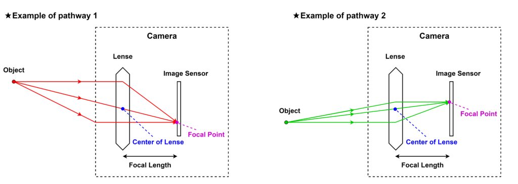
The lens has the property of focusing light by its refractive index, and by adjusting the position of the lens, the light from the object can be focused to a single point, or “focal point,” on the image sensor. The focal point is a straight line connecting the object and the center of the lens. The distance between the lens and the image sensor is called the focal length.
As the red and green lines in the above figure are both converging to a single point, it is possible to change the position of the object as long as the distance to the object remains the same. In addition, although I am showing a cross-sectional view of the camera from above, it can also be considered as a cross-sectional view from the side, since the lens has a point-symmetrical structure. In other words, the part of the image sensor in the above figure can be considered as the X-axis direction or Y-axis direction of the image. However, since the positional relationship between the object and the point on the image sensor is turned upside down, the raw image data acquired by the image sensor will be reversed vertically and horizontally from what it looks like. In order to make the final image data visible to the human eye, it is necessary to process it so that the X and Y axes are inverted.
I would also like to add a few words about the necessity of lenses. Since it is a diffuse reflection, the light reflected from a single point on the object goes in various directions. As a result, the light emitted from a single point on the object enters almost every pixel of the image sensor without a lens, and light from various places on the object gets mixed up. This makes imaging impossible. In order to limit the direction of arrival of light, there is a known method of placing a light-blocking plate in front of the image sensor, with a small hole in the center of it. This is known as the pinhole effect. This method, however, has the disadvantage of not being able to gather enough light to each pixel (each photodiode) of the image sensor to ensure a good signal-to-noise ratio (S/N), resulting in a poor image. By installing a lens instead of a small hole, the S/N can be improved by limiting the direction of arrival of light and the ability to focus light due to the refractive index of the lens.
I have explained many things, but in order to understand stereo matching in the next section, all you need to remember is that “the focus on the image sensor is on the straight line connecting the object and the center of the lens.
Stereo matching (principle of stereo camera)
Fundamentals
Stereo matching is an algorithm for estimating the distance to an object by using the fact that images captured by cameras installed at distant locations are different. The parameter that quantifies the difference in images is called “disparity”. In general, two cameras are placed horizontally on the left and right with their heights aligned. First, let’s get a sense of how the images from the left and right cameras differ in the figure below.

The left side of the figure shows the position of the object and the camera. The shape of the object is a cube with a side of 2m. The stereo camera is placed at a distance of 10 meters from the object. The height of the stereo camera is 1m from the ground. The right side of the figure shows the image taken by the camera under these conditions. The upper image is taken by the left camera and the lower image is taken by the right camera. To make comparison easier, a straight line has been drawn in the center of the horizontal direction (X-axis) of the images. Also, a straight line is drawn to mark the outline of the object in the camera (left). Relying on these straight lines for comparison, you can see that the positions of the objects in the images of the left and right cameras are misaligned. Parallax is the quantification of this shift.
The next step is to derive an equation relating parallax to distance to the object. Assuming for simplicity that the shape of the object is a “point”, we can draw the following positional diagram. For ease of viewing, we will assume that the object is in the center of the left and right cameras.
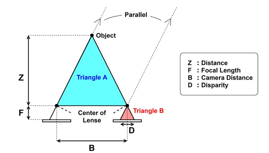
The principle of a stereo camera is that the imaging surfaces of the left and right cameras are horizontal (the two imaging surfaces are on one plane). (There are cases where the image plane is not horizontal, which will be explained later. The distance between the left and right image sensors is defined as \(B\). (B is an abbreviation for “Base Line.”) Although omitted in the figure, there is a lens directly above the image sensor, and the center of this lens is the focal point. The distance between the lens and the image sensor is the focal length \(F\). The light from the object is focused through the focal point to where it intersects the image sensor. Since the object is seen differently by the left and right cameras, the position of the pixels in the image will also be different. This shift of the image in the X-coordinate direction is the disparity \(D\). The distance to the object \(Z\) is defined as the length between the midpoint of the left and right lenses and the object.
If we define triangle A and triangle B in the above figure, they are similar. First, it should be obvious that the right side and the base of the triangle are parallel (same angle). Then, the left side of triangle B is also determined by drawing a parallel line with the line of light from the object reaching the left camera, passing through the focus of the right camera. The left side of triangle B is also determined by drawing a parallel line to the line of light from the object that reaches the left camera, passing through the focal point of the right camera. The position on the image where the object is captured by the left camera is marked on the coordinates of the right camera. In this way, we can define the disparity (D). Being similar, the relationship between the height and base of the two triangles is as follows
$$\frac{Z}{B} = \frac{F}{D}$$
Transforming this, we have an equation to find the distance \(Z\) from the disparity \(D\).
$$Z = \frac{B \times F}{D}$$
This is the basic principle of stereo cameras, that by measuring the parallax, the distance to the object can be estimated.
Applying to image data
Now we know the principle of measuring distance when the object is a single point, but it is impossible to have only one point in the actual image data. Therefore, in stereo matching, if the same “pattern” is captured by the left and right cameras, it is regarded as a point of the same object. These points are called “feature points”. The left and right cameras are placed at slightly different positions, so even though there is a parallax shift, the images will be almost identical. It will be easy to find the same pattern.
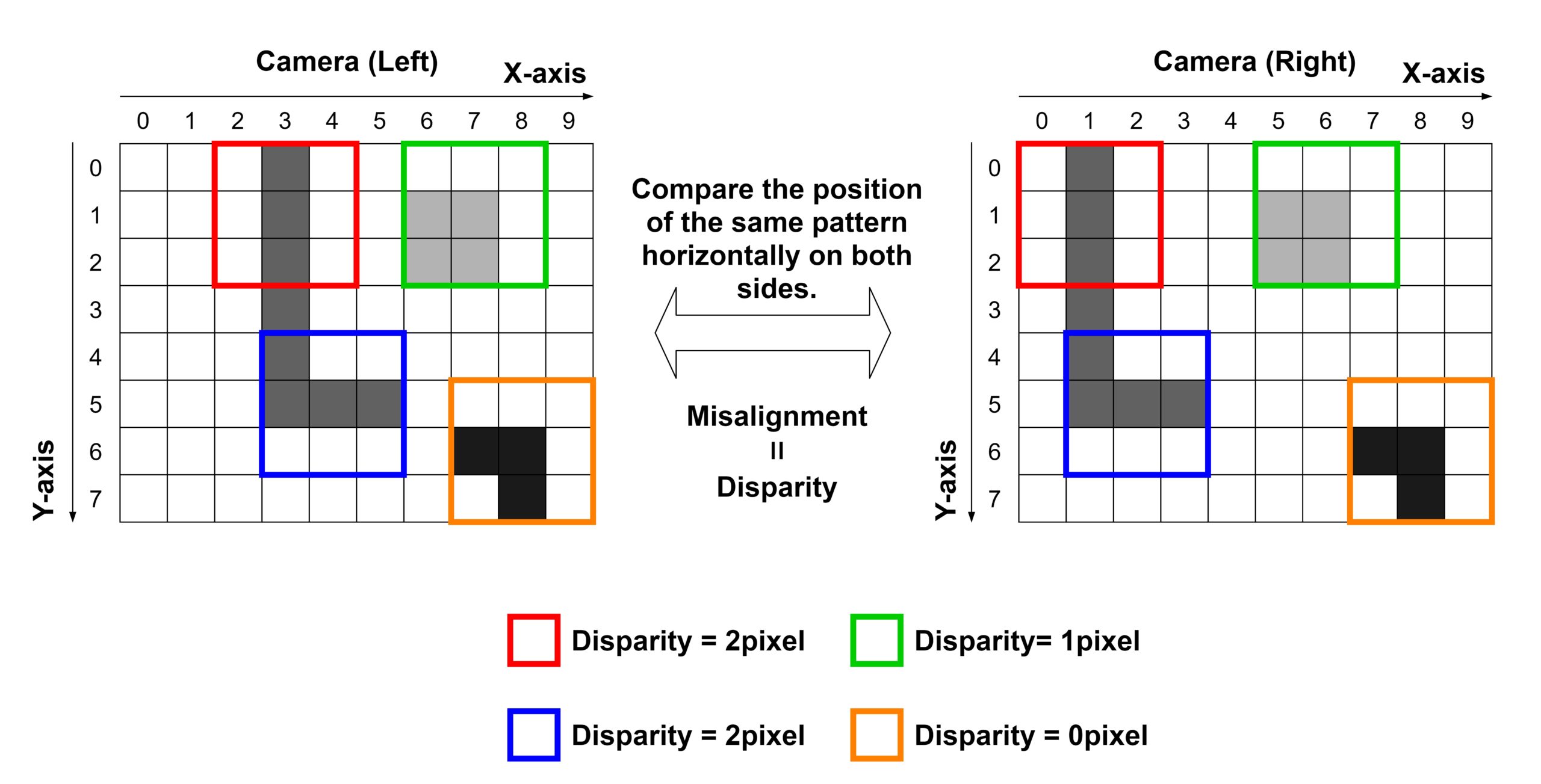
In order to find the pattern, common stereo matching converts RGB colored image data into a gray grayscale image, because in RGB, each pixel has three values: Red, Green, and Blue, making it difficult to compare. Then, using, for example, a set of 9 pixels (3 x 3) in the image data, find a place where all 9 pixels have the same value, i.e., the same pattern, in the left and right images. The figure below shows the image.

Since the left and right cameras are located far apart in the horizontal direction, parallax only occurs in the horizontal direction. Therefore, we look for the same pattern within the same height (same Y coordinate). For the sake of simplicity, let’s assume that all 9 pixels have the same value (color). In the figure, we have extracted a set of the same pattern and marked it with a frame of the same color on both sides. These are the feature points. Then, we calculate the difference between the left and right X coordinates of the same feature points, i.e., the parallax. It is common to record the disparity by superimposing it on one of the left and right images. The image is shown in the figure below.

Since 3 x 3 pixels are compared and disparity information is recorded in the center pixel, it is not possible to create a 3 x 3 pixel centered on the edge pixel. Therefore, in the above figure, the word “null” is used to indicate that there is no information. (In this example, we assume that the right side and the bottom of the pixel are also continuous, so the “edge” shown is only the left side and the top side. ) In reality, the interpolation process may fill in the disparity values for the edge pixels as well. Also, if there are several objects at different distances in the image, the disparity of each feature point will be different, and depending on their positions, there may not be a pattern of 3 x 3 pixels that perfectly matches. In the figure above, we have set such locations as null. Conversely, if there are multiple candidates for the same pattern, we also set them to null. In this example, the white pixels are like a background, and there are many places where all 3 x 3 pixels are white.
To make it easier to explain, we have used simplified image data as an example, but actual image data has “noise,” “unevenness,” “differences in reflected light depending on the angle,” and so on, and it is unlikely that the left and right images have exactly the same pattern. The following figure shows an image of actual image data.

So, the actual algorithm of stereo matching is to look for “similar patterns” instead of exactly the same pattern. To determine whether they are similar or not, the following formula is used. This formula is calculated for each pair of 3×3 pixel blocks in the left image and 3×3 pixel blocks in the right image.
$$\sum_{x,y\in B}^{} | I_L(x,y) – I_R(x,y) |$$
\(I_L(x,y)\) is the value of the pixel in the left image and \(I_R(x,y)\) is the value of the pixel in the right image. \((x,y)\) is the coordinate in a block of 3×3 pixels. \(x,y \in B\) means each \((x,y)\) coordinate within a whole block of 3×3 pixels (9 pixels total). When used in conjunction with \(\Sigma\), the process is to add 9 times. Calculate the aforementioned formula for one block in the left image and for all blocks of the same height in the right image as shown below.

The block with the lowest value in this formula is considered to be the same feature point, and the disparity is calculated between the blocks. However, if there are multiple blocks that are equally low, the calculation is considered impossible and the disparity is set to null or zero. The specific threshold value is specified by the designer. If machine learning is not used, the disparity can be tuned by hand while inputting many test images.
Stereo matching example
We would like to look at an example of the output result of the stereo matching algorithm. The figure below shows the result when the image of the cube mentioned above is input. The size of the disparity is represented by the difference in color. The redder the color, the larger the disparity and the farther the distance to the feature point.

The edge of the cube is considered as a feature point and the disparity is calculated. On the other hand, the disparity (distance) cannot be calculated for areas without feature points. Here, the parts that cannot be calculated are set to zero (blue). For the calculation, we used the function “StereoBM_create” from the open source library OpenCV. The size of the input image here is 1920 x 1080, and the block size for stereo matching is set to 15 x 15.
Stereo matching is an algorithm that estimates the distance to an object based on the pattern in the image, so if the pattern of the object is different, the result will be different. The figure below shows an example of measuring an object with a mosaic pattern on a cube of the same size as the previous example. You can see how the disparity is calculated along the pitch of the mosaic pattern. As you can see, it is a feature of stereo matching that the measurement result changes depending on the pattern. In actual stereo camera products, such as Subaru’s EyeSight for example, it is expected that more complex algorithms are used to suppress the effects of different patterns.

Stereo camera field of view
Let’s consider one of the most important parameters for a rangefinder: the field of view (measurement range). First, let’s look at how the field of view of a single camera is determined. The following figure shows the image.

Assuming the lens is large enough, the field of view is determined by the size of the image sensor (length and width) and the focal length. The larger the size of the image sensor, the wider the field of view. Image sensors are manufactured using a semiconductor process, and the larger the size, the lower the yield rate. The maximum size is a few cm square. Also, there is a relationship between the field of view and the focal length. When the distance to the object is constant, the focal length is determined by the refractive index of the lens. Since there is a limit to the control of the refractive index, the focal length cannot be infinitely reduced.
Next, consider the field of view of a stereo camera. If two cameras with the same field of view are placed horizontally, they will look like the figure below.
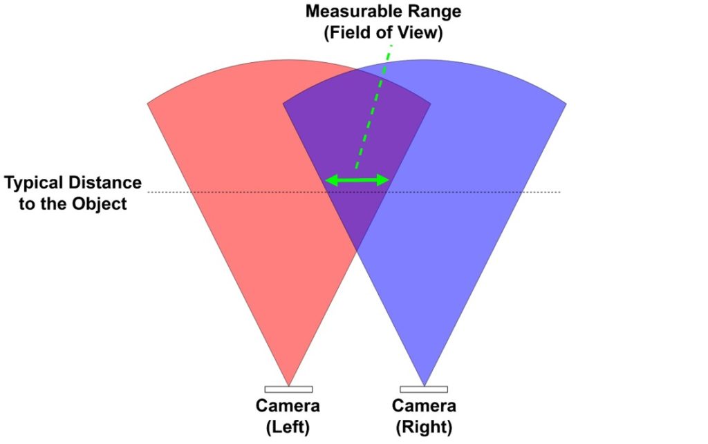
In order to perform stereo matching, the same part of the object must be visible to both cameras, so the area where the respective fields of view of the two cameras overlap is the stereo camera’s field of view. In the figure, the green arrows represent the range that can be measured at a given distance to the object. This is the field of view of the stereo camera. It depends on the distance to the object and the field of view of the camera itself, but you can see that the field of view of a stereo camera is much narrower.
In the actual product, the angle of the left and right cameras are set at different angles as shown in the figure below in order to reduce the loss of field of view. You can see how the measurement range (field of view) is clearly extended for the same distance. With this kind of ingenuity, the field of view of a stereo camera in an actual product can be as much as 150 degrees.

If you change the angle of the camera, the disparity calculation described above is no longer valid. However, it is possible to calculate the disparity by projecting the image sensor plane onto a horizontal plane and calculating the projected plane as the image sensor plane. Please refer to the following figure for the image of projection.

Angular resolution of the stereo camera
The angular resolution of a stereo camera is determined by the field of view and the number of pixels in the image sensor. Assuming that the angular resolution is \(\Delta \theta\), the field of view is \(FOV\) (Field of View), and the number of pixels is \(N\), the following formula is valid.
$$\Delta \theta = \frac{FOV}{N}$$
For example, assuming a horizontal field of view of 90°, a vertical field of view of 45°, and an image sensor with 4000 x 2000 pixels, the angular resolution in the horizontal direction is as follows.
$$\Delta \theta = \frac{90^\circ}{4000} \simeq 0.02^\circ$$
The angular resolution in the vertical direction is calculated as follows.
$$\Delta \theta = \frac{45^\circ}{2000} \simeq 0.02^\circ$$
This calculation is based on the assumption that the stereo matching process can distinguish (decompose) disparity by one pixel. In reality, it is not easy to detect the same pattern in the left and right cameras with a positional accuracy of one pixel. The above formula is only a theoretical limit. From here, it will get worse depending on the stereo matching algorithm, the S/N (signal to noise ratio) of the camera pixels, and other circumstances. In general, the actual angular resolution will be several to ten times higher than this limit. In actual products, the angular resolution can be as high as 0.1° at the best. This is considered accurate enough for normal autonomous driving robots such as self-driving cars. However, relatively inexpensive products costing several tens of thousands of yen may have an angular resolution of only 1°. This may not be sufficient for some applications.
Stereo camera distance resolution
The distance resolution of a stereo camera can be obtained from the relationship between parallax and distance. This is a recurrence and will be shown again. The distance to the object is \(Z\), the focal length is \(F\), the distance between the left and right cameras is \(B\), and the parallax is \(D\).
$$Z = \frac{B \times F}{D}$$
(B) and (F) are constants and the distance (Z) is determined by the disparity (D). The disparity is based on the minimum pixel size of the image sensor and cannot be expressed in finer values. This is the quantization error, which is the resolution of the distance. How the quantization error and other errors affect other variables through the relational equation can be determined using the error propagation formula. If the variable (Y) has multiple variables (X_0) … (X_{n-1}). This relationship can be generalized by the following formula.
$$Y = Y(X_0, …, X_{n-1})$$
At this time, if we define the error in \(Y\) as \(\Delta Y\) and the error in \(X_0\) … \(X_{n-1}\) as \(\Delta X_0\) … \(\Delta X_{n-1}\), the following relationship is established. This is the formula for error propagation.
$$\Delta Y = \sqrt{ \sum_{i=0}^{n-1} \left( \frac{\partial Y}{\partial X_i} \right)^2 (\Delta X_i)^2}$$
Let’s apply this to the equation for distance \(Z\). Since \(B\) and \(F\) are constants and not variables, the only variable is the disparity \(D\). Mathematically, the relationship can be expressed by the following equation.
$$Z = Z(D) = \left(=\frac{B \times F}{D} \right)$$
Let \(\Delta Z\) be the distance resolution. And the quantization error of the image sensor pixel size, or disparity, is \(\Delta D\). Then, the error propagation equation is as follows.
$$\Delta Z = \sqrt{ \left( \frac{\partial Z}{\partial D} \right)^2 (\Delta D)^2} = \left| – \frac{B \times F}{D^2} \times \Delta D \right| =\frac{B \times F}{D^2} \times \Delta D $$
Since we are not familiar with the parameter parallax, we will transform it into the formula for distance \(Z\).
$$D = \frac{B \times F}{Z}$$
Substitute this expression into the expression for \(\Delta Z\).
$$\Delta Z = \frac{B \times F}{D^2} \times \Delta D = B \times F \times \left(\frac{Z}{B \times F} \right)^2 \times \Delta D = \frac{Z}{B \times F} \times \Delta D$$
This is the formula for distance resolution. For example, assuming \(Z = 10[m]\), \(B = 20[cm] ~ (0.2[m])\), \(F = 5[cm] ~ (0.05[m])\), \(\Delta D = 1 [\mu m]\), the distance resolution is as follows.
$$\Delta Z = \frac{10}{0.2 \times 0.05 } \times 1 \times 10^{-6} = 1[mm] $$
Like the angular resolution, this is also a theoretical limit value, and in reality, the resolution will be several to ten times worse than this. In actual products, the distance resolution is about several mm for indoor stereo cameras with short measurement distance, and several cm to several tens of cm for those with long measurement distance such as those for automobiles. As shown in the equation, there is a proportional relationship between \(\Delta Z\) and \(Z\), so the larger the distance, the worse the distance resolution will be.
Stereo camera measurable distance (maximum distance)
The maximum distance that can be measured with a stereo camera depends on whether a parallax greater than zero can be observed. For objects of the same size, the parallax decreases with distance (inversely proportional to distance). The smallest parallax greater than zero is the pixel size of the image sensor. From this, we can calculate the theoretical limit of the maximum distance. As in the previous example, if we assume B = 0.2 [m], F = 0.05 [m], and pixel size = 1 [um], we get the following.
$$Z_{max} = \frac{B \times F}{D} = \frac{0.2 \times 0.05}{1\mu} = 10 [km]$$
10 km is a tremendously good number. It is more than enough for ground-based robots such as self-driving cars. In practice, however, it is difficult to detect parallax of a single pixel, and the amount of light available from distant objects is so small that the camera cannot capture them clearly. This is why, for example, the maximum distance for a stereo camera product for automobiles is likely to be around 150 meters.
It should be noted that stereo cameras are sometimes said to be at a disadvantage in detecting distant objects compared to millimeter wave radar and LiDAR. Millimeter wave radar and LiDAR are called “active” ranging sensors because they emit electromagnetic waves from the sensor side, while stereo cameras are called “passive” ranging sensors because they rely on ambient light to measure distance. The logic is that if you don’t emit electromagnetic waves yourself, the intensity of the electromagnetic waves you detect will be smaller, and so passive sensors are at a disadvantage. However, if the output intensity of the electromagnetic waves emitted by millimeter wave radar and LiDAR becomes too high, it may cause harm to the human body.